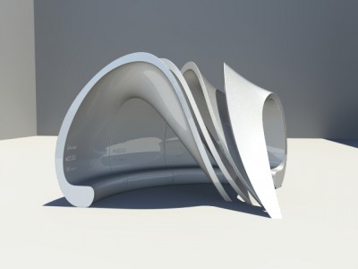
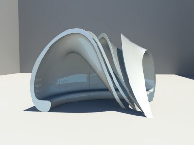
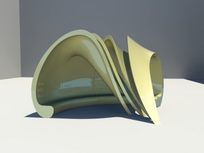
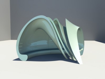
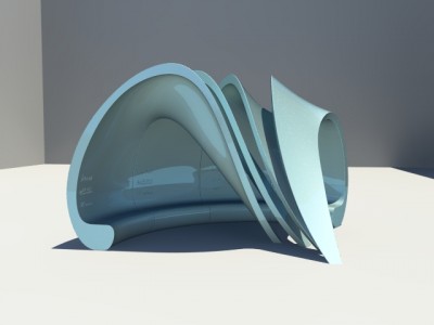
We like the Pastel Green RAL6019 the most.
Four sand holes are placed to the inner surface of the design. Two holes for filling sand which are located on the higher part of the surface, while the rest are the holes to let the sand out, located at the seat and at the end of the leg.
We try to make it simple as possible (we are quite late for the final design). We think that the holes are needed to be insert in to the mold, while the opening caps can be done separately.
We made two connection possible details for the caps which we think that they should be able to taken off and to placed back in.
In this detail, two pieces of plywood will be glued to the back of the surface. The cap will be placed inside the opening and fixed to the plywood with screws. The problem is the screws will damage the wood after using it couple of time. Which bring us to the second detail.
We change plywood into metal plates. The plate is needed to be drilled with a hole for let a bolt in, also a nut that is welted to the surface. With this detail the bolts cannot damage the metal plates. However, the metal plates are needed to be fix to the inner composite surface. The solution for now is to put the metals on the inner surface during hand lay-up process and apply extra layers on the top of the metals which will fix them into their places.
We still hope that someone might have the better idea than this. Something that is not too complicate and no visible screw or bolt head on the surface.
By the way, the new Polkima’s logo is applied to the design.
I’ve defined all the cutting planes for the mold for the leg so we can create the actual molds with the grasshopper file Hendrik will be making.
Now we have to wait until the connection group finishes the model with the actual thickness of the design and all the connections in it.
For the bench part it’s the same story: the cutting planes are defined and we have verified that it’s possible to make the molds without any undercuts.
Final design is finished and posted yesterday evening on dropbox. For the people who do not know the name yet: “Final Shape with Logos” is the correct one.
Bench is adjusted; surface of bench has a one degree slope upwards, so rain will fall off and it will be easier for the CNC. Bench height is now ergonomic 50cm.
Leg is adjusted as well; side of the smaller is now pointing outwards at the end of the leg, for easy CNC as Jelmer suggested. End of the leg is filleted.
Curves of the model can be offsetted now.
Model is made with all edges filleted and without fillet edges. Unfortunately we could not manage to fillet just the inner edges. Hopefully it is possible to combine the two for the molds somehow.
Here a preview of the placement of the logo. Renders will follow.
https://drive.google.com/folderview?id=0B–0OPeYLc2CNC1uVkpWZUZBbTA&usp=sharing
the grasshopper and rhino model it needs some grass hopper troubleshooting
An idea of the lid that is used to close the filling sand hole. The red part are composite material and the white part can be made out of two layers of plywood (needed to be simplified).
Plywood and its cover (same material with the rest of the design) can be glued or bolted together. After close the lid, turn it 90 degrees to lock. The bottom surface (the square surface) is the surface of the design.
If you have any idea for the lid, please post it. We really need it!
Today I’ve been working on defining the best angle and cutting planes for the molds for the leg.
For this I used a grasshopper script we created to check for undercuts. This script uses a Galapagos block to minimize the amount of undercuts; of course the script should end up finding a orientation for the molds which causes no undercuts.
Sadly, I only partly succeeded. When analyzing the inner surface I found the making of the molds wouldn’t be possible without a few undercuts (and I informed the design group about this.)

The picture above is a top view of the inner surface, rotated so the undercuts are minimized. The green arrows is where undercuts still happen if we would have to make this part. With the connection methods we’re currently planning to use. So this is the part that should be fixed.
I also came across a similar problem for the filleted edges on the outer surface, but I think that’s is something to discuss we have planned on Monday. (Because I think there might be an easier fix for this.)
Even though the molds will end up to be unmakeable using the current design I decide on how to divide the them. To create actual mold-models from these cut parts Hendrik will be creating a grasshopper file which will also automatically create the needed margin and edges. (Or at least, that’s the plan.)
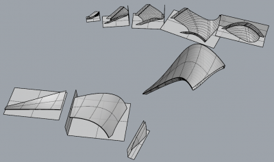
I have divided the molds like this;

The parts in the previous picture will be milled separately and then be put together to create one big mold for the inner surface and one for the outer surface of the leg. The (small) molds for the bench part will be put together separately. To make it clear, the completely model is currently divided (big-mold wise) like this, with the inner and outer surface separated;

Update [11/03/2014]: the undercut problem has been solved by adjusting the design and the cutting plane for the molds just a little bit. The division for the molds only changed a little bit.