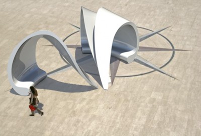

Four sand holes are placed to the inner surface of the design. Two holes for filling sand which are located on the higher part of the surface, while the rest are the holes to let the sand out, located at the seat and at the end of the leg.
We try to make it simple as possible (we are quite late for the final design). We think that the holes are needed to be insert in to the mold, while the opening caps can be done separately.
We made two connection possible details for the caps which we think that they should be able to taken off and to placed back in.
In this detail, two pieces of plywood will be glued to the back of the surface. The cap will be placed inside the opening and fixed to the plywood with screws. The problem is the screws will damage the wood after using it couple of time. Which bring us to the second detail.
We change plywood into metal plates. The plate is needed to be drilled with a hole for let a bolt in, also a nut that is welted to the surface. With this detail the bolts cannot damage the metal plates. However, the metal plates are needed to be fix to the inner composite surface. The solution for now is to put the metals on the inner surface during hand lay-up process and apply extra layers on the top of the metals which will fix them into their places.
We still hope that someone might have the better idea than this. Something that is not too complicate and no visible screw or bolt head on the surface.
By the way, the new Polkima’s logo is applied to the design.
An idea of the lid that is used to close the filling sand hole. The red part are composite material and the white part can be made out of two layers of plywood (needed to be simplified).
Plywood and its cover (same material with the rest of the design) can be glued or bolted together. After close the lid, turn it 90 degrees to lock. The bottom surface (the square surface) is the surface of the design.
If you have any idea for the lid, please post it. We really need it!
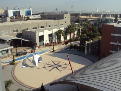
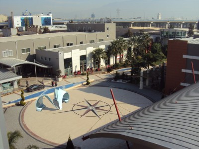
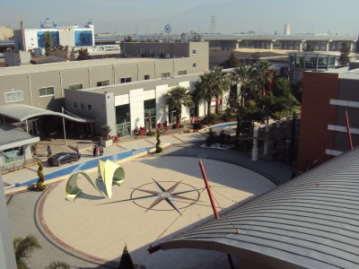
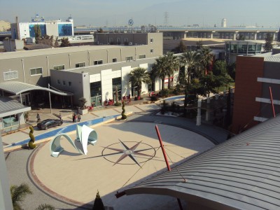
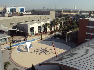
Our “In and Around” design for preliminary. Above are all the rendering in many locations.
These are the colour test. In the end our conclusion is red.
These are the assembling process. The design have to be made out of two part, upper and lower part, which will be laminated together at the edges. After the glue stiffs enough, the edges need to be sanded and painted to get rid of the exposed composite edge.
We improved our model. In this new update, there are two arches in the design which each of them consist of two similar parts. Then, there are four parts in the design that can be made by the same mold. It decrease mold area to 17.3 m2.
Also, we decide to use lamination method to assembling the model because it seems to be the only way to keep the shape edges. After laminating, the edge of the composite needs to be sanded and painted to create a nice looking finishing.