Grid to ensure the right position and form:

Principle of the scaffolding for now, will be elaborated in the coming days:


Grid to ensure the right position and form:
Principle of the scaffolding for now, will be elaborated in the coming days:


The final molds are done!
There are four panels, thus four combined molds, A, B, C and D.
We followed the elephant logo for naming, From left to right and top to bottom. A – B forms the top part, C -D forms the bottom part.

The molds can be found here:
https://www.dropbox.com/sh/fhc6txh6m3n6zod/au8y99ix3g
The created molds have arrows for the milling direction and names:

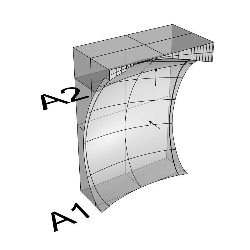


We like the Pastel Green RAL6019 the most.
Four sand holes are placed to the inner surface of the design. Two holes for filling sand which are located on the higher part of the surface, while the rest are the holes to let the sand out, located at the seat and at the end of the leg.


We try to make it simple as possible (we are quite late for the final design). We think that the holes are needed to be insert in to the mold, while the opening caps can be done separately.
We made two connection possible details for the caps which we think that they should be able to taken off and to placed back in.

In this detail, two pieces of plywood will be glued to the back of the surface. The cap will be placed inside the opening and fixed to the plywood with screws. The problem is the screws will damage the wood after using it couple of time. Which bring us to the second detail.
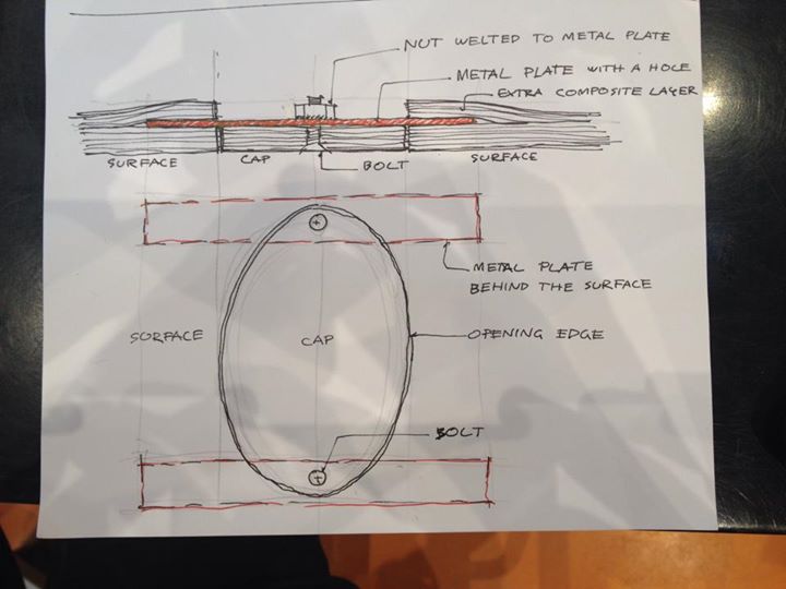
We change plywood into metal plates. The plate is needed to be drilled with a hole for let a bolt in, also a nut that is welted to the surface. With this detail the bolts cannot damage the metal plates. However, the metal plates are needed to be fix to the inner composite surface. The solution for now is to put the metals on the inner surface during hand lay-up process and apply extra layers on the top of the metals which will fix them into their places.
We still hope that someone might have the better idea than this. Something that is not too complicate and no visible screw or bolt head on the surface.
By the way, the new Polkima’s logo is applied to the design.
I’ve defined all the cutting planes for the mold for the leg so we can create the actual molds with the grasshopper file Hendrik will be making.
Now we have to wait until the connection group finishes the model with the actual thickness of the design and all the connections in it.
For the bench part it’s the same story: the cutting planes are defined and we have verified that it’s possible to make the molds without any undercuts.

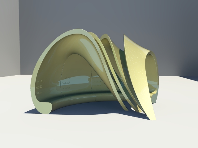
Final design is finished and posted yesterday evening on dropbox. For the people who do not know the name yet: “Final Shape with Logos” is the correct one.
Bench is adjusted; surface of bench has a one degree slope upwards, so rain will fall off and it will be easier for the CNC. Bench height is now ergonomic 50cm.
Leg is adjusted as well; side of the smaller is now pointing outwards at the end of the leg, for easy CNC as Jelmer suggested. End of the leg is filleted.
Curves of the model can be offsetted now.
Model is made with all edges filleted and without fillet edges. Unfortunately we could not manage to fillet just the inner edges. Hopefully it is possible to combine the two for the molds somehow.
Here a preview of the placement of the logo. Renders will follow.


https://drive.google.com/folderview?id=0B–0OPeYLc2CNC1uVkpWZUZBbTA&usp=sharing
the grasshopper and rhino model it needs some grass hopper troubleshooting