All posts by Jelmer Niesten

The finished product

After one week of working hard, the actual product got finished.
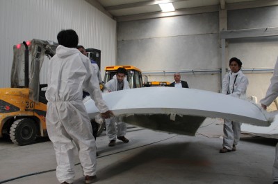
At the end of the  building week it got transported to Yasar University. And after a small presentation we all enjoyed the great and shiny object we produced.

The arrival;

OLYMPUS DIGITAL CAMERA OLYMPUS DIGITAL CAMERA OLYMPUS DIGITAL CAMERA

The final product;

OLYMPUS DIGITAL CAMERA OLYMPUS DIGITAL CAMERA OLYMPUS DIGITAL CAMERA OLYMPUS DIGITAL CAMERA


A big thanks to everybody who worked so hard to realize this amazing project!


Factory days

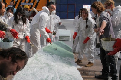
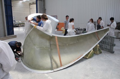
Today we present our design at the Yasar University, so it’s time for a wrap up of the week here in Izmir. After some guided tours and relaxing on the beach, we started working on the piece.

Hand layup:IMG_2369

Panels from the molds:
IMG_2399

Cutting the edges:
IMG_2401

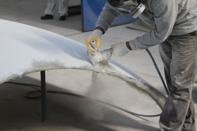
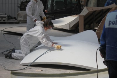
Sanding:
IMG_2419

Creating the inner part:
IMG_2434

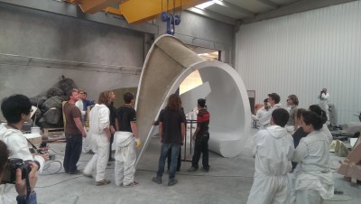
The piece standing upright:
IMAG0213


Today the object is finished and will be placed at the Yasar University campus.

Maarten & Luuk

Molds for the leg: continued

I’ve defined all the cutting planes for the mold for the leg so we can create the actual molds with the grasshopper file Hendrik will be making.
Now we have to wait until the connection group finishes the model with the actual thickness of the design and all the connections in it.

For the bench part it’s the same story: the cutting planes are defined and we have verified that it’s possible to make the molds without any undercuts.

New_molds_example
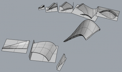
On this picture you can see the complete leg part, the cutting planes/’molds’ for the outer surface (bottom left) and the cutting planes/’molds’ for the inner surface and the sides (top right.)

Molds for the leg: the story so far

Today I’ve been working on defining the best angle and cutting planes for the molds for the leg.
For this I used a grasshopper script we created to check for undercuts. This script uses a Galapagos block to minimize the amount of undercuts; of course the script should end up finding a orientation for the molds which causes no undercuts.

Sadly, I only partly succeeded. When analyzing the inner surface I found the making of the molds wouldn’t be possible without a few undercuts (and I informed the design group about this.)
Mold leg undercuts
The picture above is a top view of the inner surface, rotated so the undercuts are minimized. The green arrows is where undercuts still happen if we would have to make this part. With the connection methods we’re currently planning to use. So this is the part that should be fixed.

I also came across a similar problem for the filleted edges on the outer surface, but I think that’s is something to discuss we have planned on Monday. (Because I think there might be an easier fix for this.)

Even though the molds will end up to be unmakeable using the current design I decide on how to divide the them. To create actual mold-models from these cut parts Hendrik will be creating a grasshopper file which will also automatically create the needed margin and edges. (Or at least, that’s the plan.)
I have divided the molds like this;
Molds leg

The parts in the previous picture will be milled separately and then be put together to create one big mold for the inner surface and one for the outer surface of the leg. The (small) molds for the bench part will be put together separately. To make it clear, the completely model is currently divided (big-mold wise) like this, with the inner and outer surface separated;
Division model


Update [11/03/2014]: the undercut problem has been solved by adjusting the design and the cutting plane for the molds just a little bit. The division for the molds only changed a little bit.

Preliminary design presentation group 2: the dance

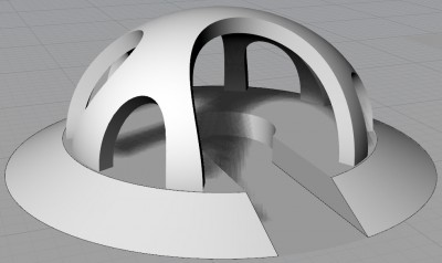
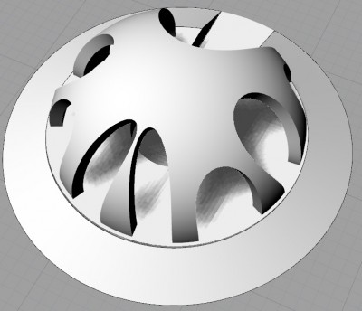
‘The Dance’ is meant to be an iconic meeting spot, shelter, rest place which would be modular and buildable.
It would be doable within the 20m² mold restriction and because of it’s modularity it would be easy to create fewer or even more parts and arrange them according to the local demands.

The Dance - Slide1

Click here to download the complete presentation as pdf.

Jelmer Group 2 Further developments design

Today we from group 2 continued on further developing our design. For this we took our final design from last week and the comments on it.
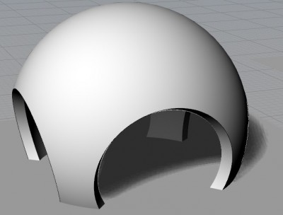
The most important was to make sure the design would fit into the molds. Therefore we decided that we make our design so we could use our mold three times. (The design below now has a surface of 19 m² per part, so it should fit in the available molds/mold space.)
After defining the main shape and separation of the parts we individually made some variants, below you can see mine.
Tomorrow we will further discuss them and hopefully pick one to refine.

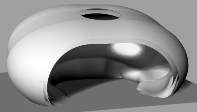
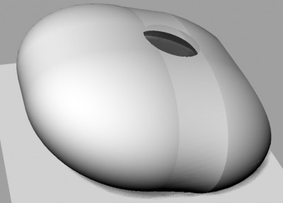
Two variants, one very smooth and another one with some curves on the surface which makes it look more interesting (sadly it looks pretty weird on the render, I should probably change the used curves a bit to fix this.)
Jelmer Sketch Design Further Development


Different variants of the separate part (from very smooth to a curved/non smooth surface.)
Jelmer Sketch Design Further Development Jelmer Sketch Design Further Development